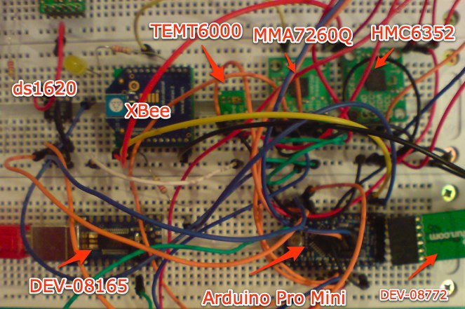
I finally put together an Arduino Pro Mini, the XBee, the MMA7260Q, the HMC6352, the TEMT6000 and the DS1620.
This is how it looks like on the prototyping board (ugly, I know)
Hopefully it would look better when I move it to the PCB. But before doing that I need to get the battery power set up. (I’m waiting for a MAX756 DC-DC voltage regulator and CoilCraft inductors to arrive)
The XBee uses the API mode and I implemented a Zigbee Application Layer protocol stack in Arduino instead of using the Serial interface like the rest of Arduino-XBee project that I’ve seen.
I implemented the Temperature Measurement Cluster ID (0x0402) and the Illuminance Measurement Cluster ID (0x0400) (see Zigbee Cluster Library ). Then I also two non-standard cluster ids, the Tilt Measurement Cluster ID (0xFC00) and the Heading Measurement Cluster ID (0xFC01).
You can download the source code for the Arduino project.
Below you can find the main project file, from here I pass the control to the Xbee library and control the sleep cycle of the Arduino. The XBee library will invoke the callbacks (fgetTemperature, etc) when it needs the data. ie. it receives a read command. The callbacks(function pointers) point to functions in the main file (readDs1620, readTEMT6000, etc) and the callbacks are implemented in this main file which also contains the calls to ds1620 library, hmc6352 library and mma7260q library. To see the source files of the libraries download the sources. I also made independent libraries for ds1620, hmc6352 and mma7260q each one containing an example.
The code (also as gist):
/*
XBee sensor
ZCL Temperature Measurement Cluster
*/

#define ledPin 13

#define lcdPin 6
#define temt6000Pin 3

#include <stdlib.h>
#include <math.h>

#include <Stdio.h>
#include <SoftwareSerial.h>
#include <avr/power.h>
#include <avr/sleep.h>
#include "XBeeLibrary.h"
#include "ds1620.h"
#include <Wire.h>
#include "hmc6352.h"
#include <math.h>
#include <float.h>
#include <limits.h>

int xaxis = 0;
int yaxis = 1;
int zaxis = 2;

float xa=0;
float ya=0;
float za=0;

int minx = INT_MAX;
int maxx = 0;
int miny = INT_MAX;
int maxy = 0;
int minz = INT_MAX;
int maxz = 0;

float g0x = 0;
float g0y = 0;
float g0z = 0;

//long time1 = 0;
//long time2 = 0;

// set up a new serial port
SoftwareSerial lcdSerial = SoftwareSerial(lcdPin,lcdPin);
byte pinState[16];
byte backlightValue = 0x9D;

// set up ds1620
Ds1620 ds1620 = Ds1620(7/*rst*/,8/*clk*/,9/*dq*/);

//set up hmc6352
Hmc6352 hmc6352;

void setup() {
  pinMode(ledPin, OUTPUT);
  pinMode(lcdPin, OUTPUT);
  pinMode(temt6000Pin,INPUT);
  pinMode(xaxis,INPUT);
  pinMode(yaxis,INPUT);
  pinMode(zaxis,INPUT);

  // set the data rate for the SoftwareSerial port
  lcdSerial.begin(4800);

  Serial.begin(9600);
  delay(100);

  // configure ds1620
  ds1620.config();

  //initial calibration of the MMA7260q
  minx = 173.0;
  miny = 192.0;
  minz = 258.0;

  maxx = 766.0;
  maxy = 720.0;
  maxz = 914.0;

  g0x = 469.0;
  g0y = 456.0;
  g0z = 586.0;

  lcdPrint("RST\r\n");delay(100);
}

long start =0;

void loop()
{
  struct zigbee zb;
  unsigned long time;
  unsigned long time2;

  xbee_init(&zb);
  zb.fgetTemperature = &readDs1620;
  zb.fprogress = &toggleLedPin;
  zb.ferror = &lcdPrint;
  zb.fprint = &lcdPrint;
  zb.fprintHex = &lcdPrintBuffer;
  zb.fgetHeading = &readHmc6352;
  zb.fgetIlluminance = &readTEMT6000;
  zb.fgetTilt = readMMA7260Q;

  XBee xbee(&zb);

  time = 0;
  time2 = 0;

  //lcdPrintInt(millis());
  while(1)
  {
    xbee.serve();
    if ((millis()-time) > 500) {
      time = millis();
      toggle(ledPin);
      //lcdSerial.print("ab\r\n");
    }

    int pfx /*valx*/ = analogRead(xaxis); // read the value from the sensor
    int pfy /*valy*/ = analogRead(yaxis); // read the value from the sensor
    int pfz /*valz*/ = analogRead(zaxis); // read the value from the sensor

    autoZeroCalibration(pfx,pfy,pfz);

    if ((millis()-time2) > 25000) {
      goToSleep();
      time2 = millis();
    }
  }
}

void goToSleep()
{
  /* Now is the time to set the sleep mode. In the Atmega8 datasheet
  * http://www.atmel.com/dyn/resources/prod_documents/doc2486.pdf on page 35
  * there is a list of sleep modes which explains which clocks and
  * wake up sources are available in which sleep modus.
  *
  * In the avr/sleep.h file, the call names of these sleep modus are to be found:
  *
  * The 5 different modes are:
  * SLEEP_MODE_IDLE -the least power savings
  * SLEEP_MODE_ADC
  * SLEEP_MODE_PWR_SAVE
  * SLEEP_MODE_STANDBY
  * SLEEP_MODE_PWR_DOWN -the most power savings
  *
  */

  set_sleep_mode(SLEEP_MODE_IDLE); // sleep mode is set here

  sleep_enable(); // enables the sleep bit in the mcucr register
  // so sleep is possible. just a safety pin

  power_adc_disable();
  power_spi_disable();
  power_timer0_disable();
  power_timer1_disable();
  power_timer2_disable();
  power_twi_disable();

  digitalWrite(ledPin, 0);
  lcdPrint("slp\r\n");

  sleep_mode(); // here the device is actually put to sleep!!

  digitalWrite(ledPin, 1);
  lcdPrint("wk\r\n");

  // THE PROGRAM CONTINUES FROM HERE AFTER WAKING UP
  sleep_disable(); // first thing after waking from sleep:
  // disable sleep...

  power_all_enable();

}

void toggleLedPin() {
  toggle(ledPin);
}

float readDs1620()
{
  ds1620.start_conv();
  int raw_data = ds1620.read_data();
  ds1620.stop_conv();
  float temp = raw_data / 2.0;
  return temp;
}

float readHmc6352()
{
  hmc6352.wake();
  float a = hmc6352.getHeading();
  hmc6352.sleep();

  return a;

}

void toggle(int pinNum) {
  // set the LED pin using the pinState variable:
  digitalWrite(pinNum, pinState[pinNum]);
  // if pinState = 0, set it to 1, and vice versa:
  pinState[pinNum] = !pinState[pinNum];
}

int readTEMT6000()
{
  int val = analogRead(temt6000Pin);
  return val;
}

float readMMA7260Q(int a)
{
  int pfx /*valx*/ = analogRead(xaxis); // read the value from the sensor
  int pfy /*valy*/ = analogRead(yaxis); // read the value from the sensor
  int pfz /*valz*/ = analogRead(zaxis); // read the value from the sensor

  autoZeroCalibration(pfx,pfy,pfz);

  int fx = (pfx - g0x);
  int fy = (pfy - g0y);
  int fz = (pfz - g0z);

  float ax = (fx*2.0)/((maxx-minx));
  float ay = (fy*2.0)/((maxy-miny));
  float az = (fz*2.0)/((maxz-minz));

  float rho = atan(ax/sqrt(pow(ay,2)+pow(az,2)))*(57.2957795129); //57.2957795129 degrees per rad
  float phi = atan(ay/sqrt(pow(ax,2)+pow(az,2)))*(57.2957795129);
  float theta = atan(sqrt(pow(ay,2)+pow(ax,2))/az)*(57.2957795129);

  switch (a)
  {
    case 1:
      return rho;
      break;
    case 2:
      return phi;
      break;
    case 3:
      return theta;
      break;
    default:
      break;
  }
  return 0;
}

void autoZeroCalibration(int pfx, int pfy, int pfz)
{
  //if ((pfx < minx)||(pfy < miny)||(pfz < minz)||(pfx > maxx)||(pfy > maxy)||(pfz > maxz)) {
  // autozero calibration
  if (pfx < minx) minx = pfx;
  if (pfy < miny) miny = pfy;
  if (pfz < minz) minz = pfz;

  if (pfx > maxx) maxx = pfx;
  if (pfy > maxy) maxy = pfy;
  if (pfz > maxz) maxz = pfz;

  g0x = ((maxx - minx)/2)+minx;
  g0y = ((maxy - miny)/2)+miny;
  g0z = ((maxz - minz)/2)+minz;

  //printValues();
  //}
}

////////////////////////////////////
//// Print functions
//////////////////////////////////

//void lcdPrintError(char *msg)
//{
// lcdSerial.print("err:");
// lcdSerial.print(msg);
//}

void lcdPrint(char *msg)
{
//lcdSerial.print(millis());
//lcdSerial.print(":");
// lcdSerial.print(msg);
}

//void lcdPrintInt(long i)
//{
// lcdSerial.print(i, DEC);
//}

//void lcdPrintHex(byte *hex, int size)
//{
// for(int i=0;i<size;i++)
//  {
    //lcdPrintHex(hex[i]);
//  }
//}

void lcdPrintBuffer(byte *hex, int size)
{
  //lcdPrintHex(hex,size);
  //lcdPrintBuffer(hex,size,"buf");
}

//void lcdPrintBuffer(byte *hex, int size, char *msg)
//{

  //int i = 0;
  //while (i<size) {
    //lcdSerial.print(msg);
    //lcdSerial.print(" ");
    //lcdSerial.print(i);
    //lcdSerial.print("-");
    //lcdSerial.print(i+7);
    //lcdSerial.print("\r\n");
    //int len = min(size-i,8);
    //lcdPrintHex(hex+i,len);
    //lcdSerial.print("\r\n");
    //i=i+8;
  //}
 // lcdSerial.print("\r\n");
//}

//void lcdPrintHex(byte hex)
//{
//  lcdSerial.print((hex&0xF0)>>4,HEX);
// lcdSerial.print((hex&0x0F),HEX);
//}
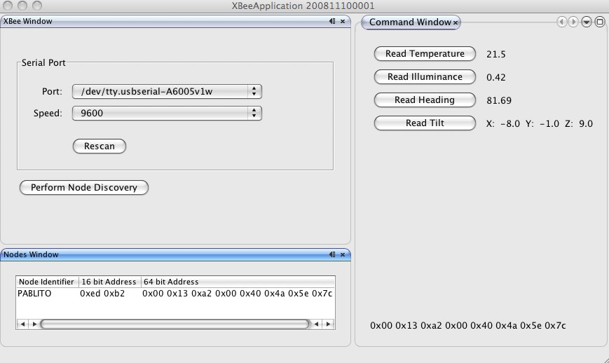
This is the java gui I built to test the implementation
The DEV-08165 is a Serial USB Board from Sparkfun. I use it to get logs from the Arduino, the logs are outputed in serial form on pin 6 , because the serial port (USART) on the ATmega is being used for the XBee communication. The DEV-8772 is the board to program the Arduino Pro Mini, the pro mini does have an USB connector on board like other Arduinos, you need the DEV-8722 to program it/power it
Reference

